A new roof over the Engineering Courtyard
Studies on Pattern and FormPrinceton University
Rafael Pastrana & Edvard Bruun
✏️ Intro
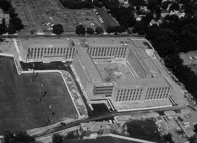
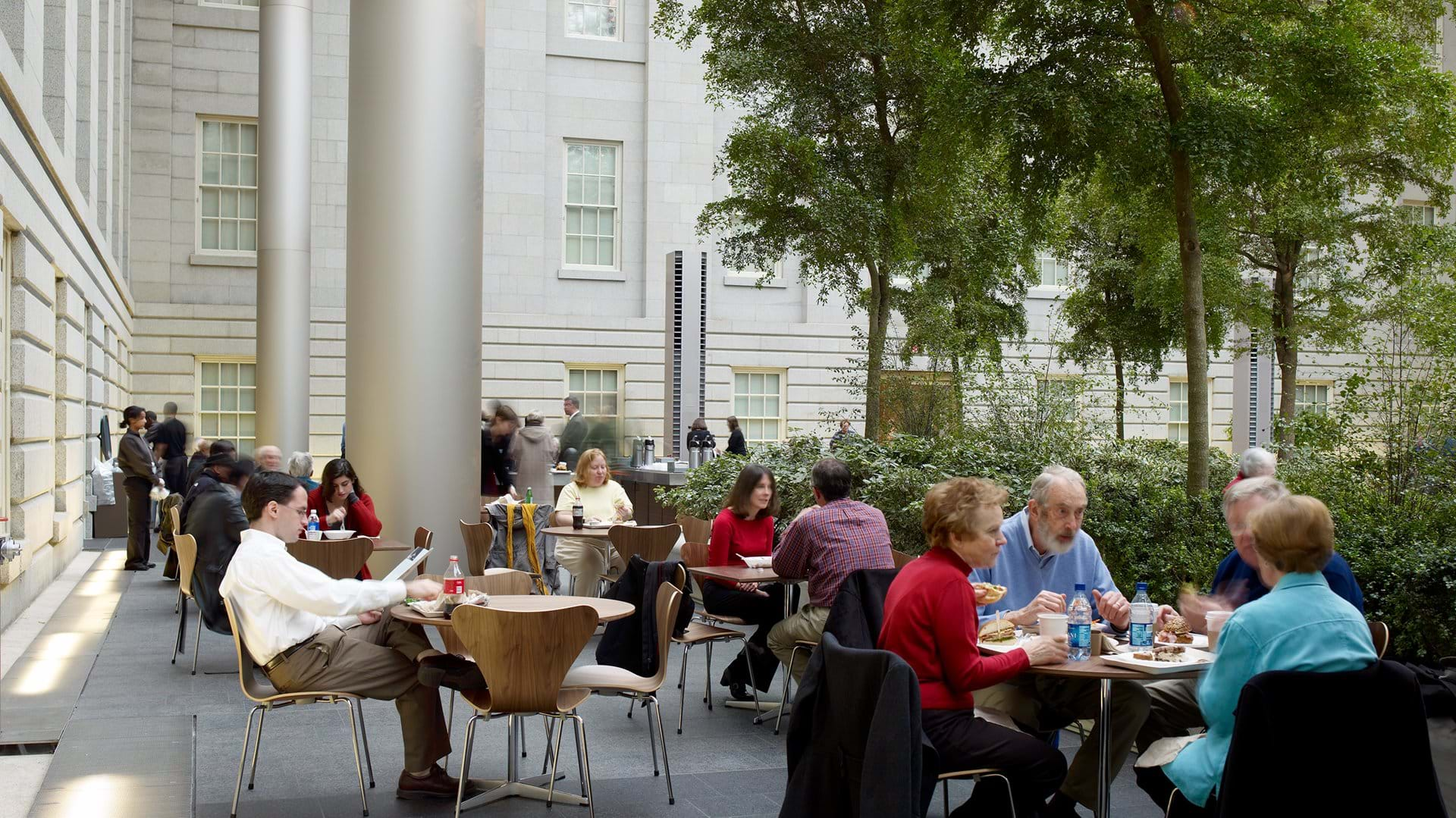
To celebrate its golden jubilee, the School of Engineering and Applied Sciences at Princeton University has decided to invest in the expansion of its facilities. The creation of an iconic roof structure over the courtyard of the existing Engineering Quadrangle has therefore been proposed. In line with the School’s commitment to the integration of the scientific and artistic disciplines, the space generated at the ground level is envisioned as an appealing tinker space that cultivates collaboration and enables the free and joyful exchange of ideas. The only restriction posed is with respect to visual discreteness: the height of the new roof should not exceed that of the Quadrangle, at 16.50 m, by more than one meter.
🏡 Architectural Concept
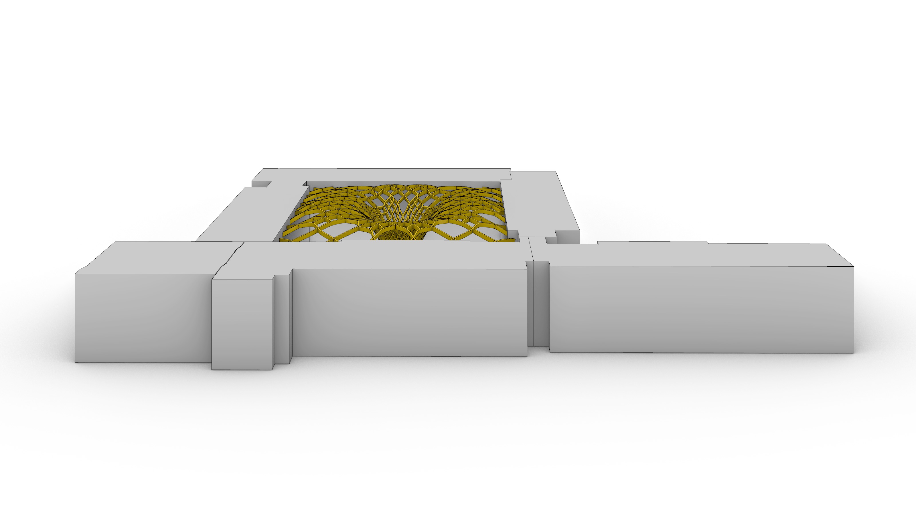
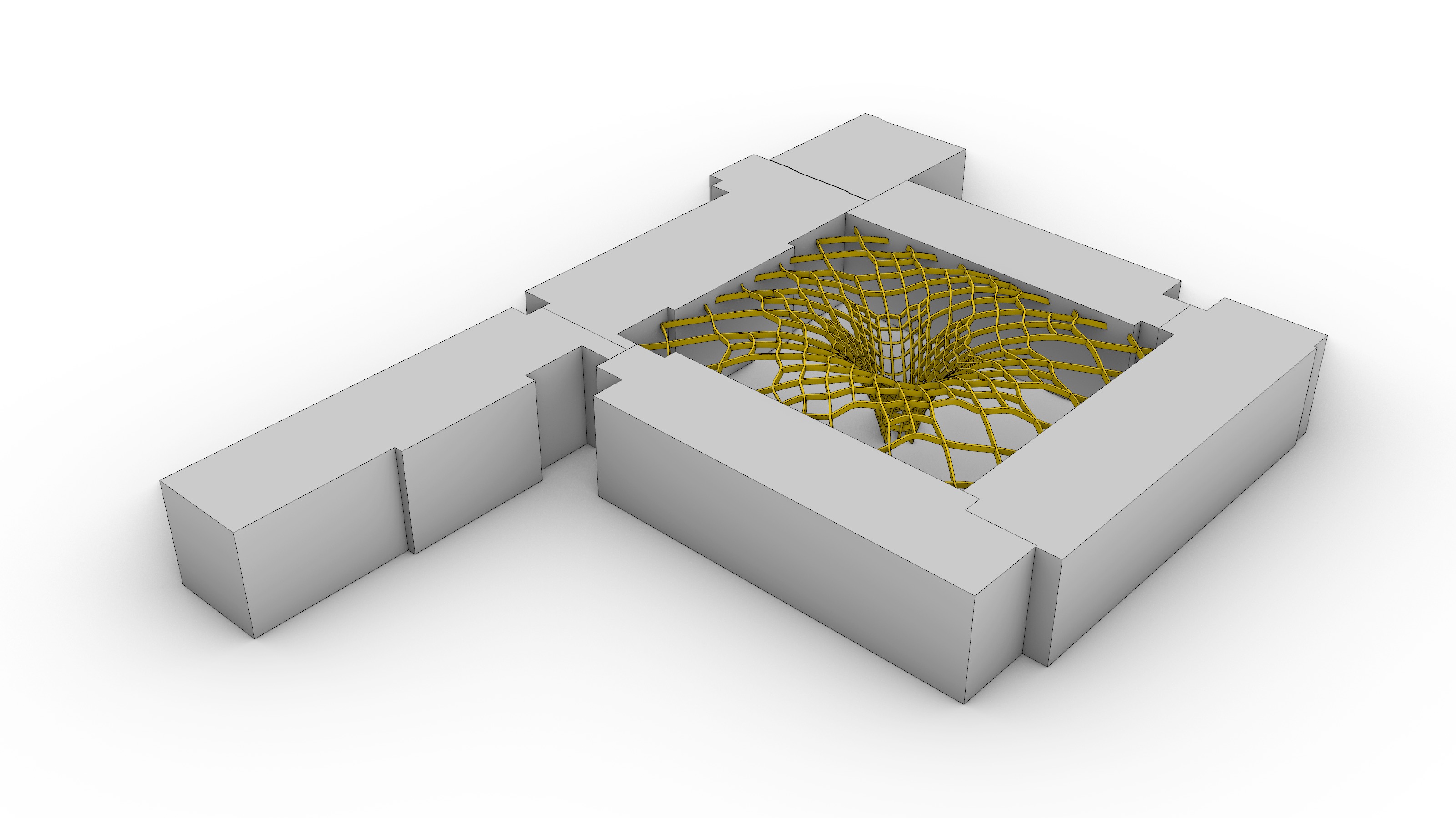
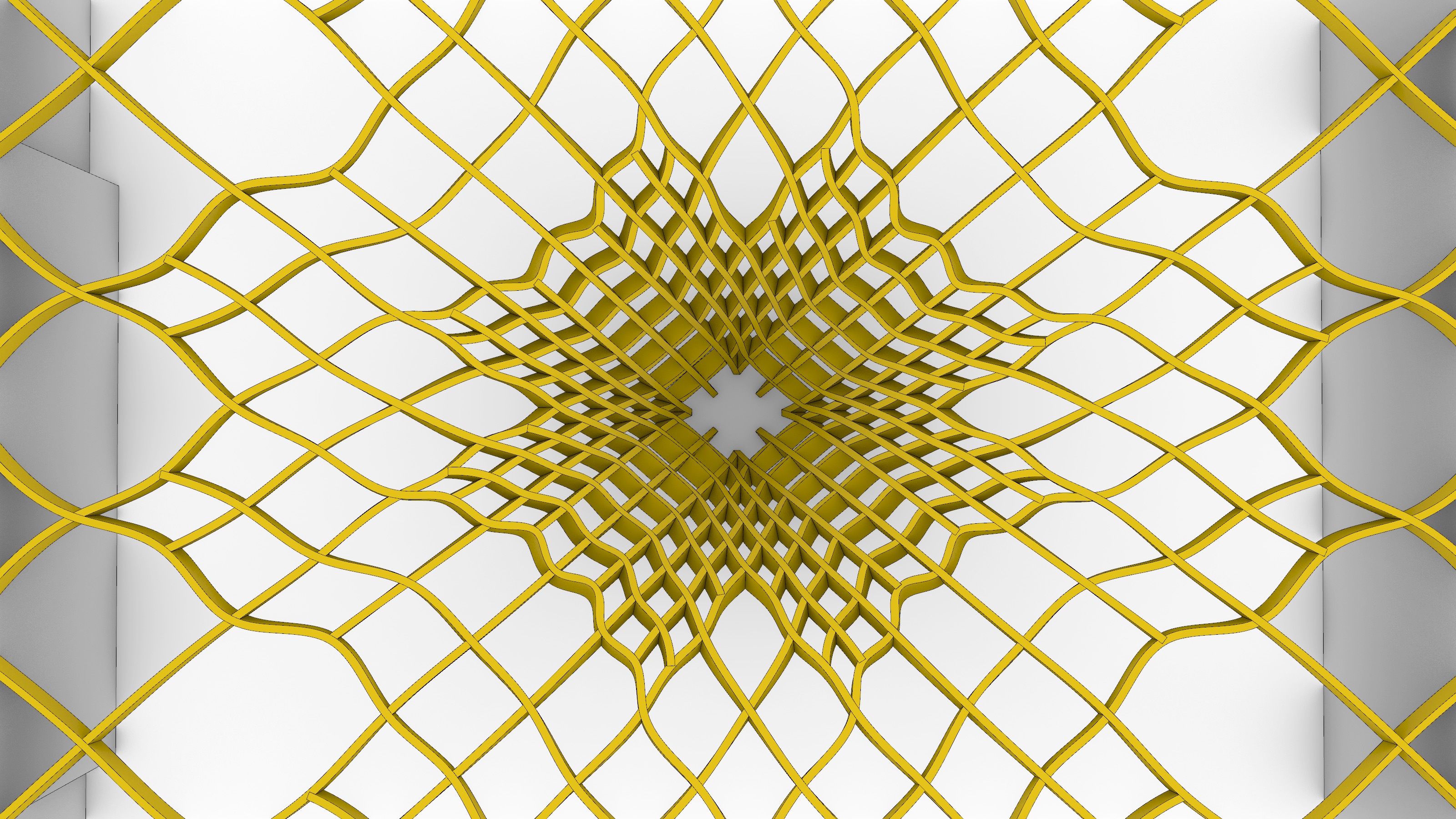
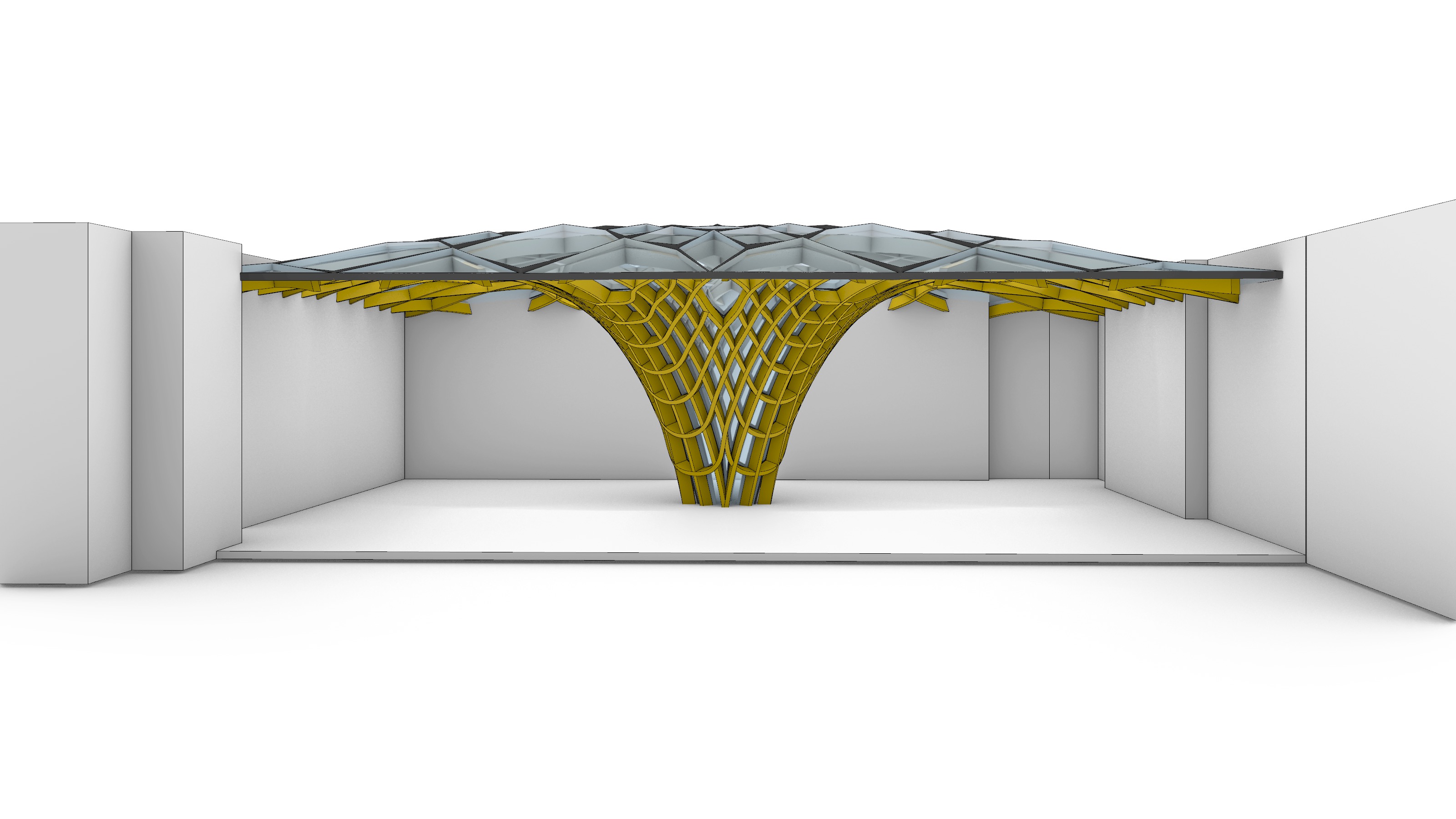
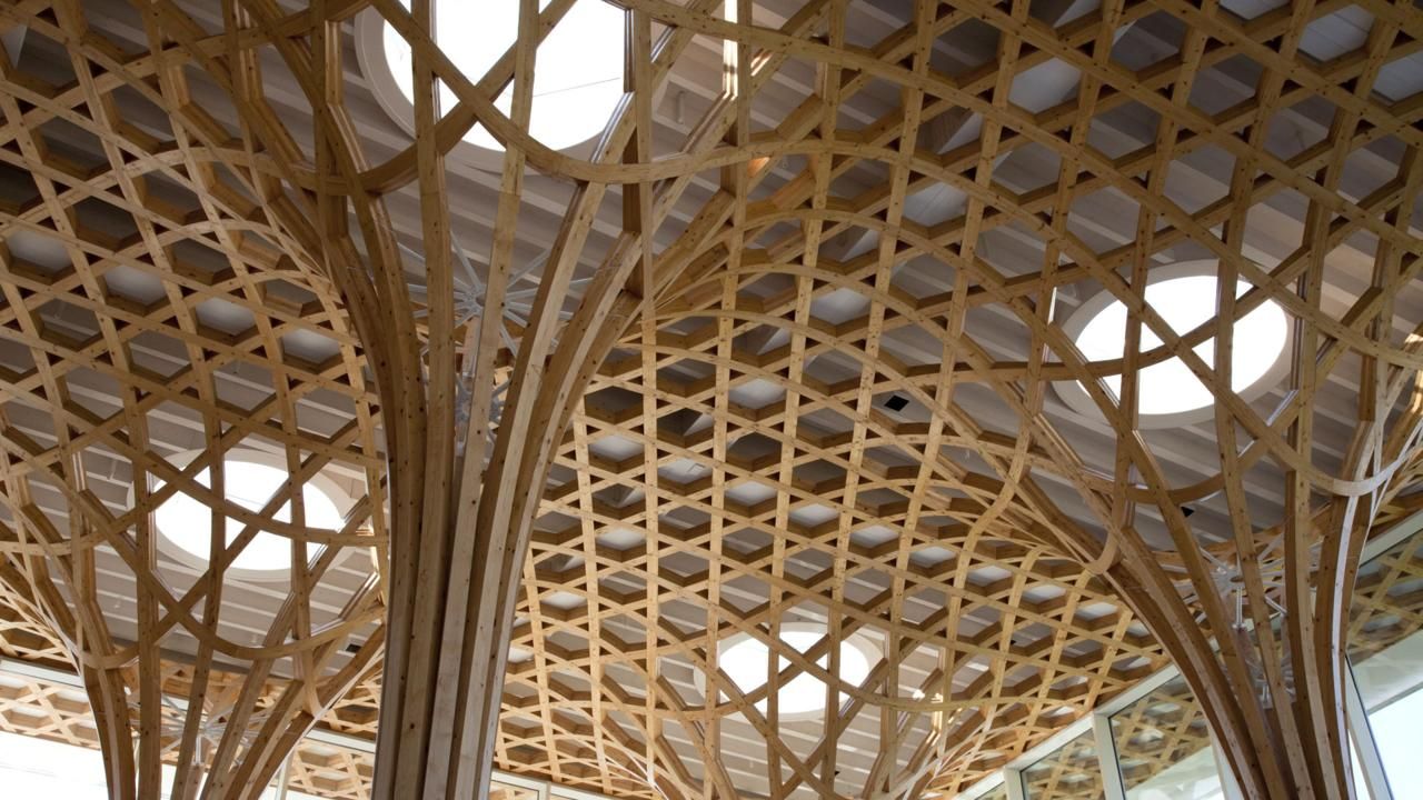
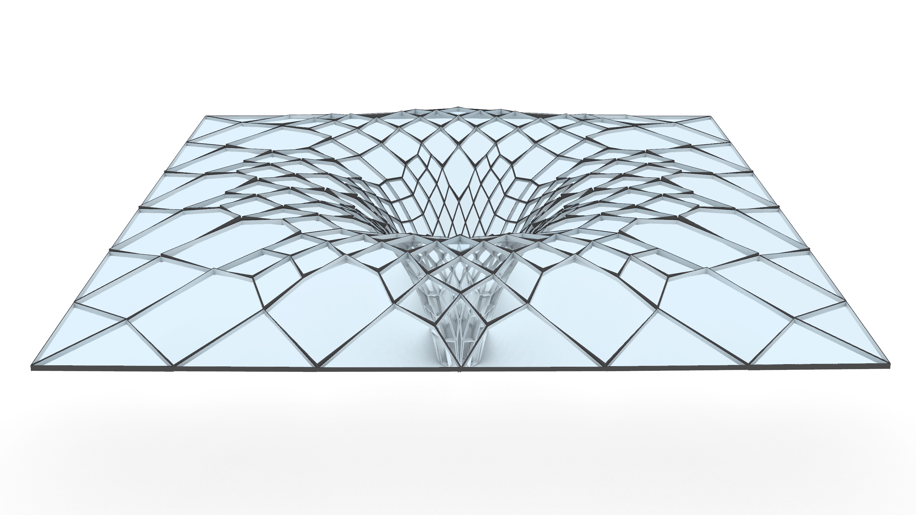
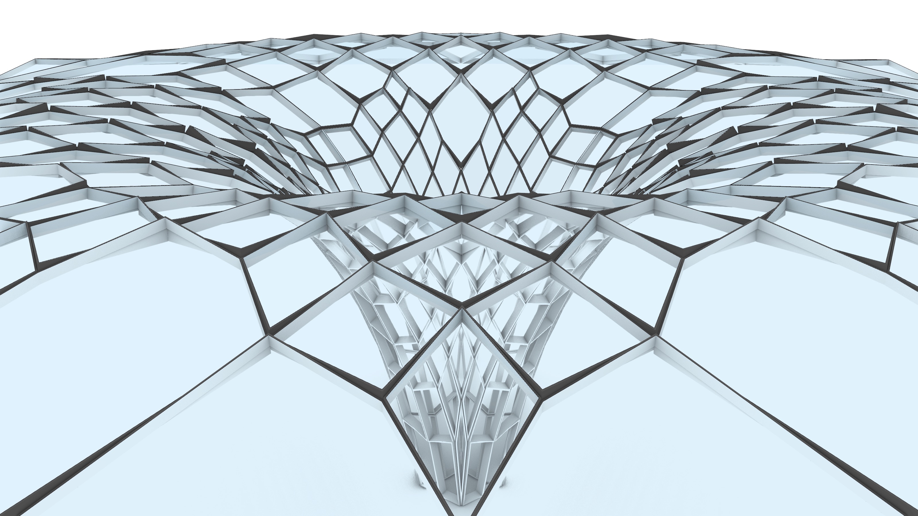
The notion of a garden becomes the medullary piece of the architectural vision for this project. What if we learned, gathered and researched in a space embedded in nature? Inspired by other successful precedents in the field, the project proposes to revitalize the existing garden around a landmark gridshell structure which, like a tree, stems from the very center of the courtyard, and morphs from a solid trunk at the base into a filigree of leaves at the tip of its branches.
The fibrous-like roof structure seeks to reflect on the values of transparency, unity, and cohesion that characterize academic endeavors, and with a single gesture, strives to amalgamate the buildings surrounding the courtyard. With an average span of 60.0 m and 53.0 m in the longitudinal and transversal directions respectively, the resulting geometry of the roof gridshell is the output of a computational approach that reconciles structure and form: the shape is not explicitly drafted but rather found. Furthermore, due to recent technological developments in mass timber production and procuring the storage of carbon from the atmosphere in buildings, glulam is imagined as a suitable material solution to materialize the roof.
🕹 Form-Finding
a. Dynamic Relaxation
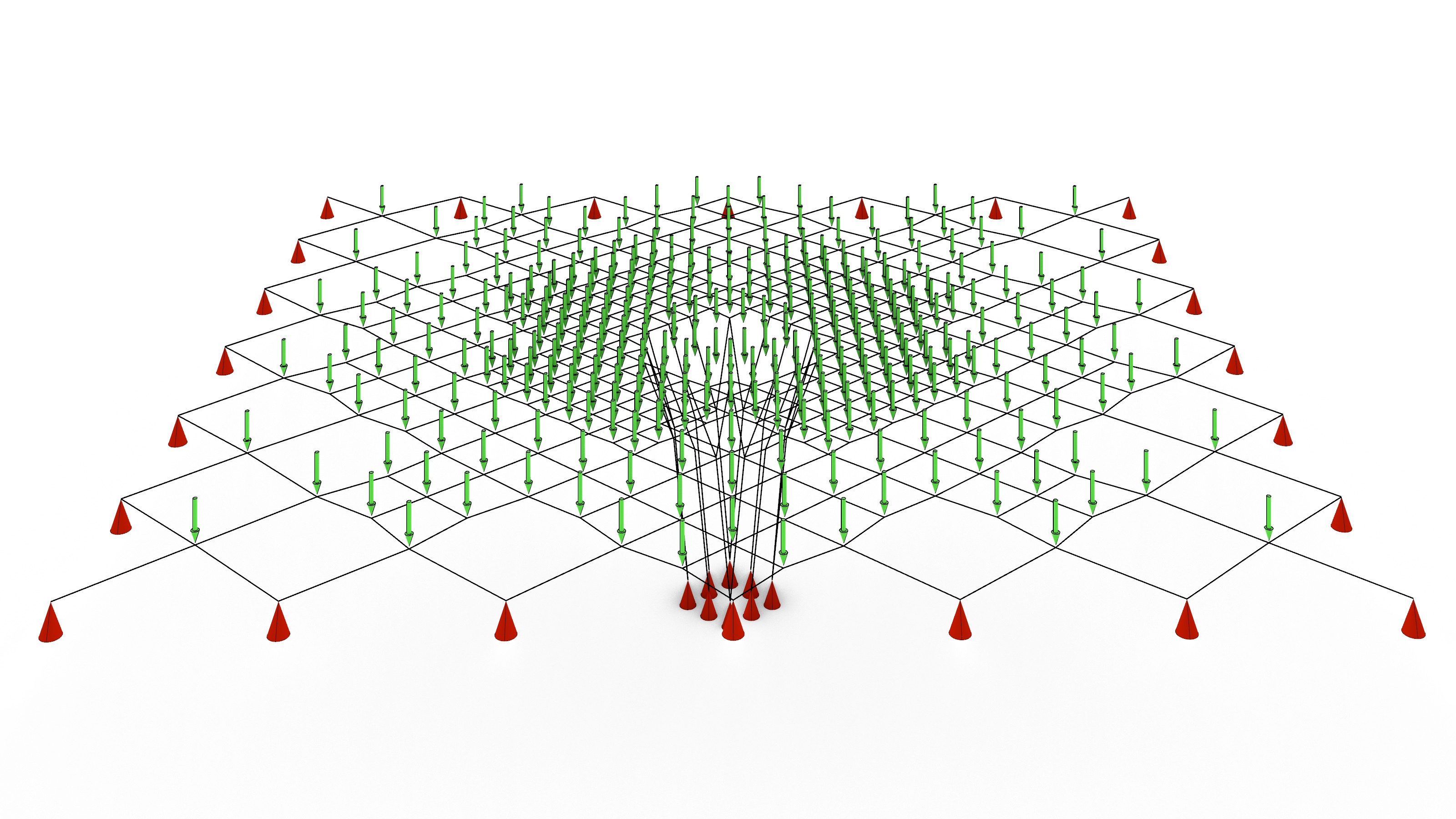
To uncover a form in equilibrium the Dynamic Relaxation Method (DR) by De Laet et al, 2013 was explored. The iterative nature of the form-finding process is illustrated in the animation above for the chosen design option. It is worth noting that a pre-existing computational implementation was very valuable to speed up the evaluation of a handful of different structural alternatives.
The gridshell roof was abstracted as a network of vertices and edges, where the former represent hinged nodal connections and the latter, prismatic beam elements with axial and bending stiffness. As for the support conditions, the roof is assumed to be pinned-supported on all the vertices around the perimeter at the roof level, as well as those at the ground level where the middle touchdown column is present (red cones in the diagram above). For the sake of simplicity and unless explicitly stated hereafter, the following generalized parameters were adopted during the form-finding process: point loads p=10 kN were applied at every node (green arrows in the diagram above); a force-density of q=10.0, an elasticity modulus E=10 N/mm2, and a cross-section area A=10 mm2 were assigned to all the beam elements in the system.

b. Sensitivity Analysis
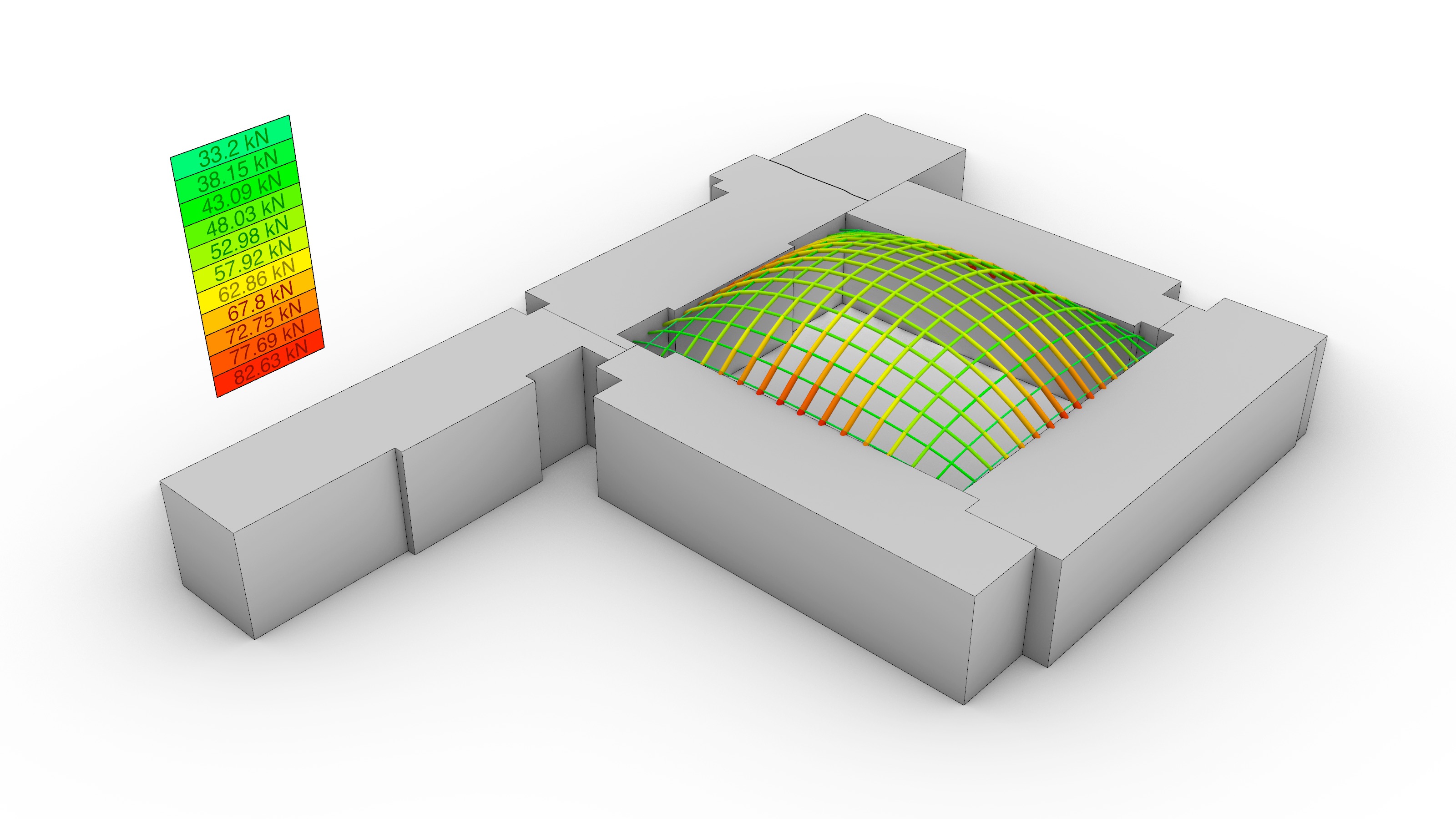
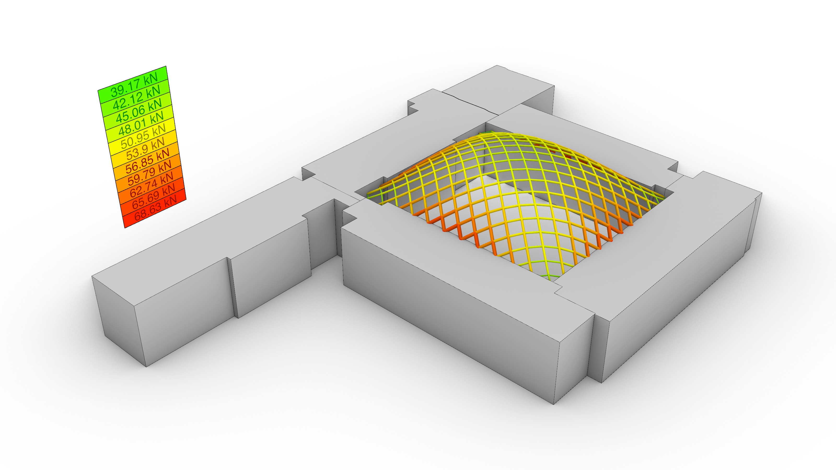
The topology of the equilibrium solution was directly interpreted as the geometry of the gridshell. Hence, it was relevant to evaluate the performance of a few different alternatives in terms of the total force distribution: the amount of force transmitted to the existing building, and the total height of the generated form. A parametric sensitivity analysis was carried out looking at four options: 1) a traditional 90º grid, 2) a 45º grid, 3) a 45º grid with a central column, and 4) 45º gradually-subdivided grid with a central column, which was the selected choice.
The average cell dimension for every alternative was of 3.35 x 3.35 m, except in the subdivided variant where modules of 1.67 x 1.67, 3.35 x 3.35, and 6.70 x 6.70 m were present. To make a fair comparison across design solutions, the total cumulative edge length of all studied proposals amounted to 2.00 km (+- 0.08). When the maximum height of the equilibrium solution was deliberately restricted, the target height was set to 17.00 m (+- 0.50) in compliance with the brief’s requirement to not go 1.00 m over the Engineering Quadrangle’s estimated height (16.50 m).
Furthermore, limiting the amount of horizontal thrust that was to be transferred to the surrounding buildings was an important consideration. As opposed to other precedents where, for instance, thrust could only be directed towards the corners of the surrounding existing buildings, the selected solution was planned to direct the horizontal forces that arise at the roof level directly to the perimeter of the existing concrete slabs. This is because as structural diaphragms, they can drag the loads from the roof into the stair and elevator cores.
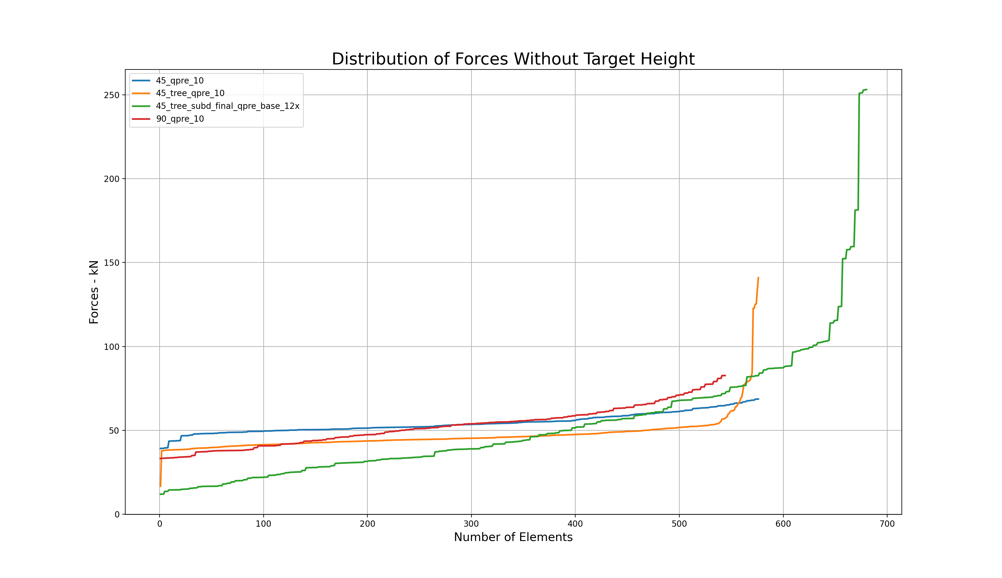
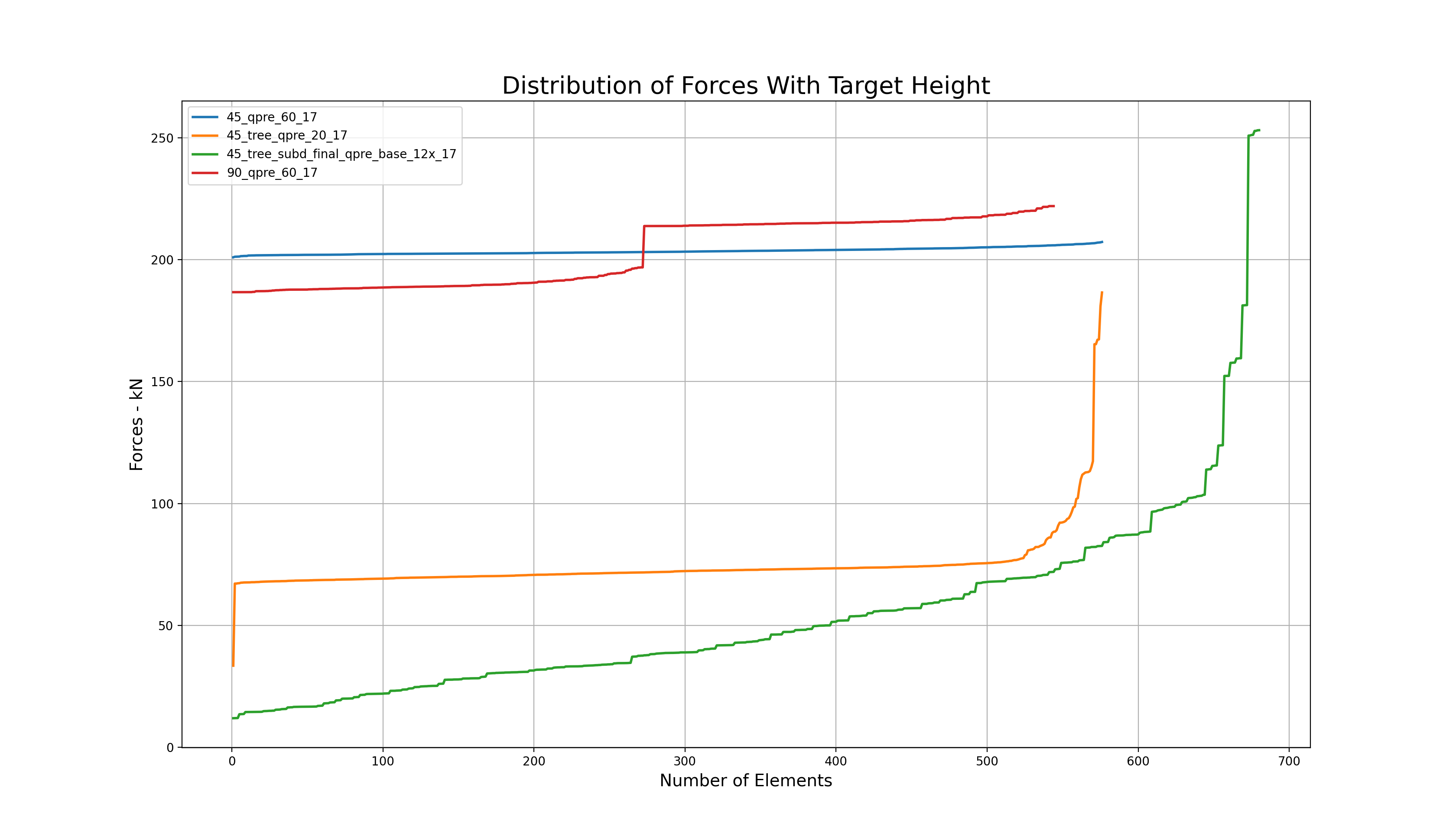
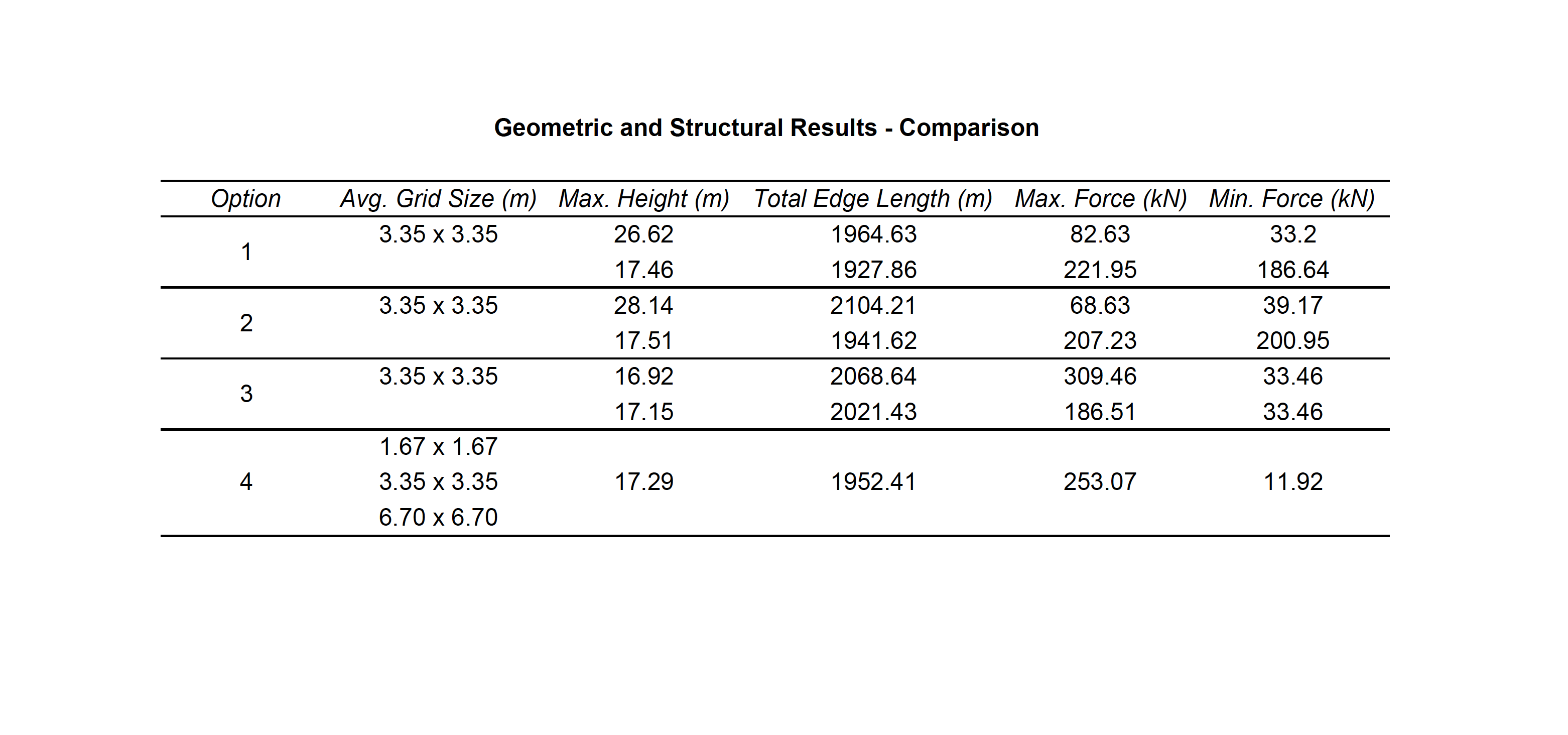
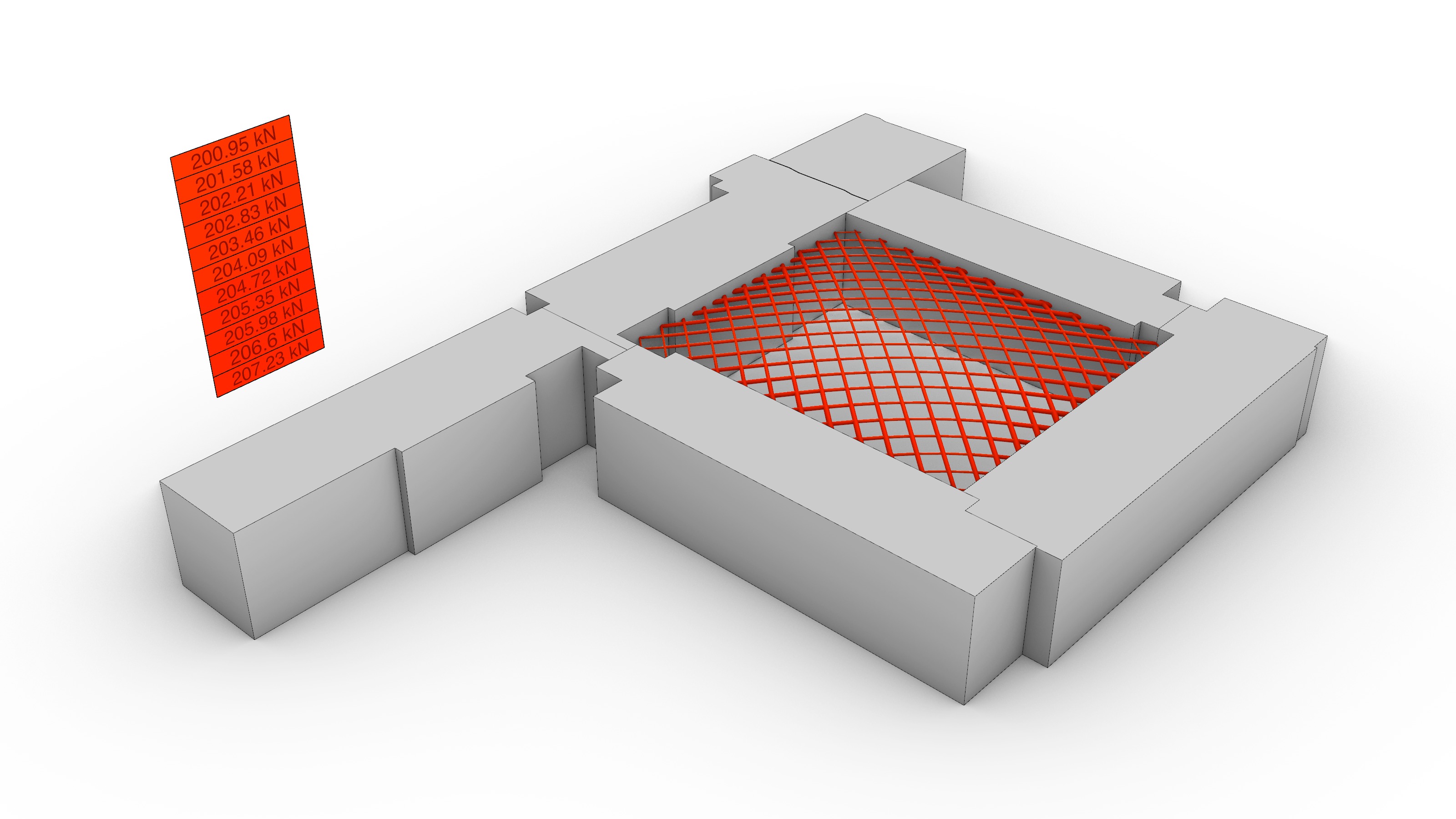
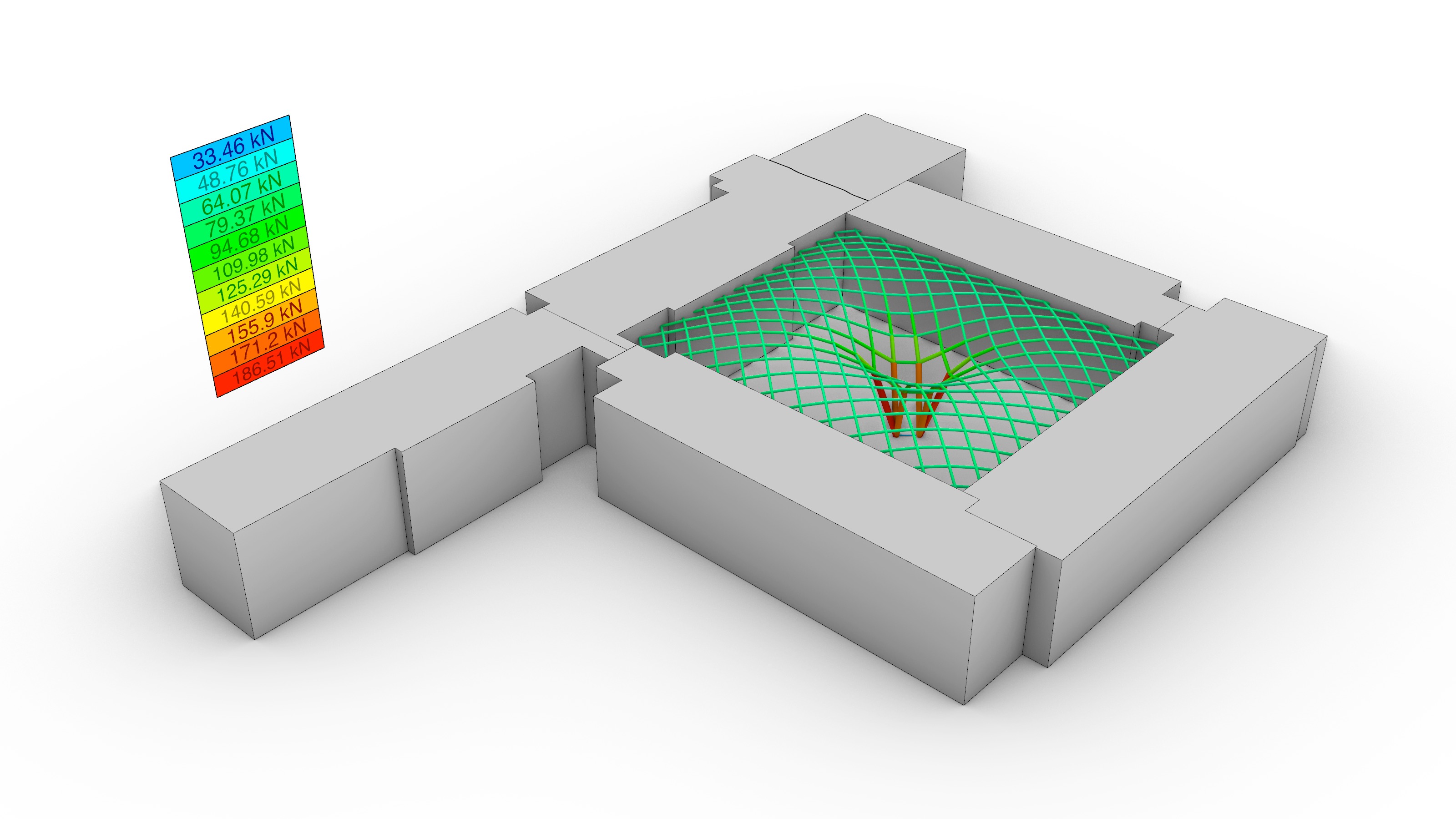
The results of the sensitivity analysis are shown in the graphs and the table above. In sum, the findings can be clustered in two sets: those where the maximum height was left to the algorithm to be found based on the initial force densities q, and those where the values of q had to be deliberately adjusted to achieve compliance with the height restrictions. In other words, without and with a target height. The line colors in the graphs are red, blue, orange and green for options 1), 2), 3) and 4) respectively.
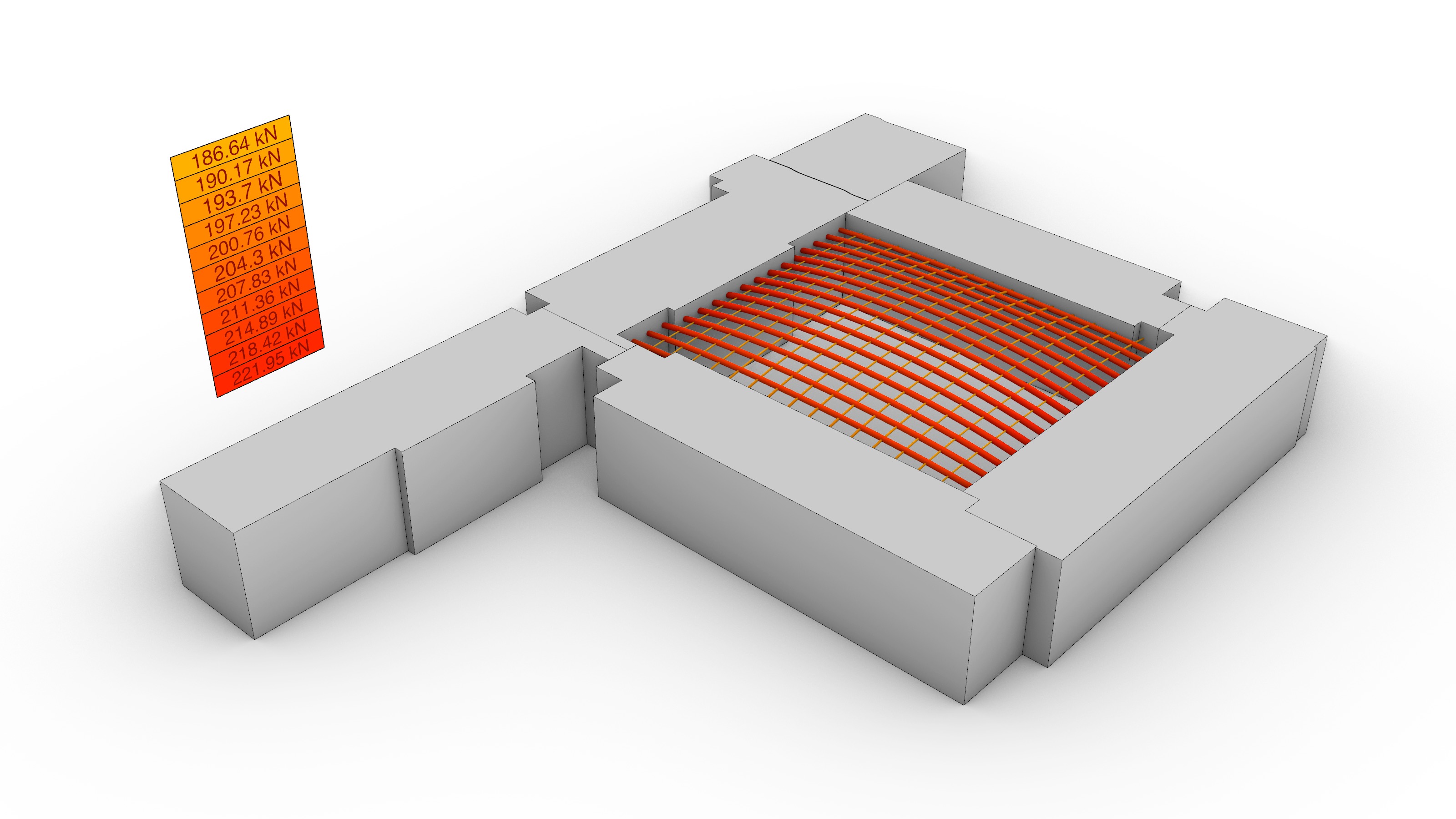
Overall, while options 1) and 2) share a smooth force distribution that overall resembles a linear trend, the options with a central support in the courtyard experience a noticeable force surge towards the end of the graph because a large portion of forces is being transferred directly to the groundvia column action. The unselected options 1), 2) and 3) seem to be structurally more efficient than the final choice in green without a target height. Nevertheless, when the maximum allowable height is enforced, there is a 180º-degree turn in the data: while options 1) and 2) still follow a linear, almost-flat trend, the compression forces in their systems exhibit a four-fold increase from an average of 50 kN to roughly 200 kN; thus diminishing their structural suitability. On the contrary, the final choice 4) had already fulfilled the height constraint from the very beginning and its force distribution remained positively unchanged.
It is worth clarifying the amount by which the force densities q were modified in options 1), 2) and 3) to comply with the target height. For the first two, the initial value of q was set to q=60.0, and for 3), to q=20.0. Furthermore, it is also important to elaborate on the reasoning behind the subdivision scheme featured by 4). After a careful look at option 3), it was detected that the resulting length of the column-like elements at the central touch-down point, which coincidentally carried the highest loads, was significantly high (13.60 m), and constituted a major concern with respect to buckling. Motivated by this, a graded subdivision scheme that restrained the buckling length of the elements of the gridshell was implemented, on top of an adjustment of q=120.0 in all the elements that were in direct contact with the ground. The outcome of this modification is favorable: although the maximum compression force at the base rose for the chosen option from 186 kN to 253 kN, the maximum element buckling length was decreased by a factor of four, from 13.60 m to 3.35 m.
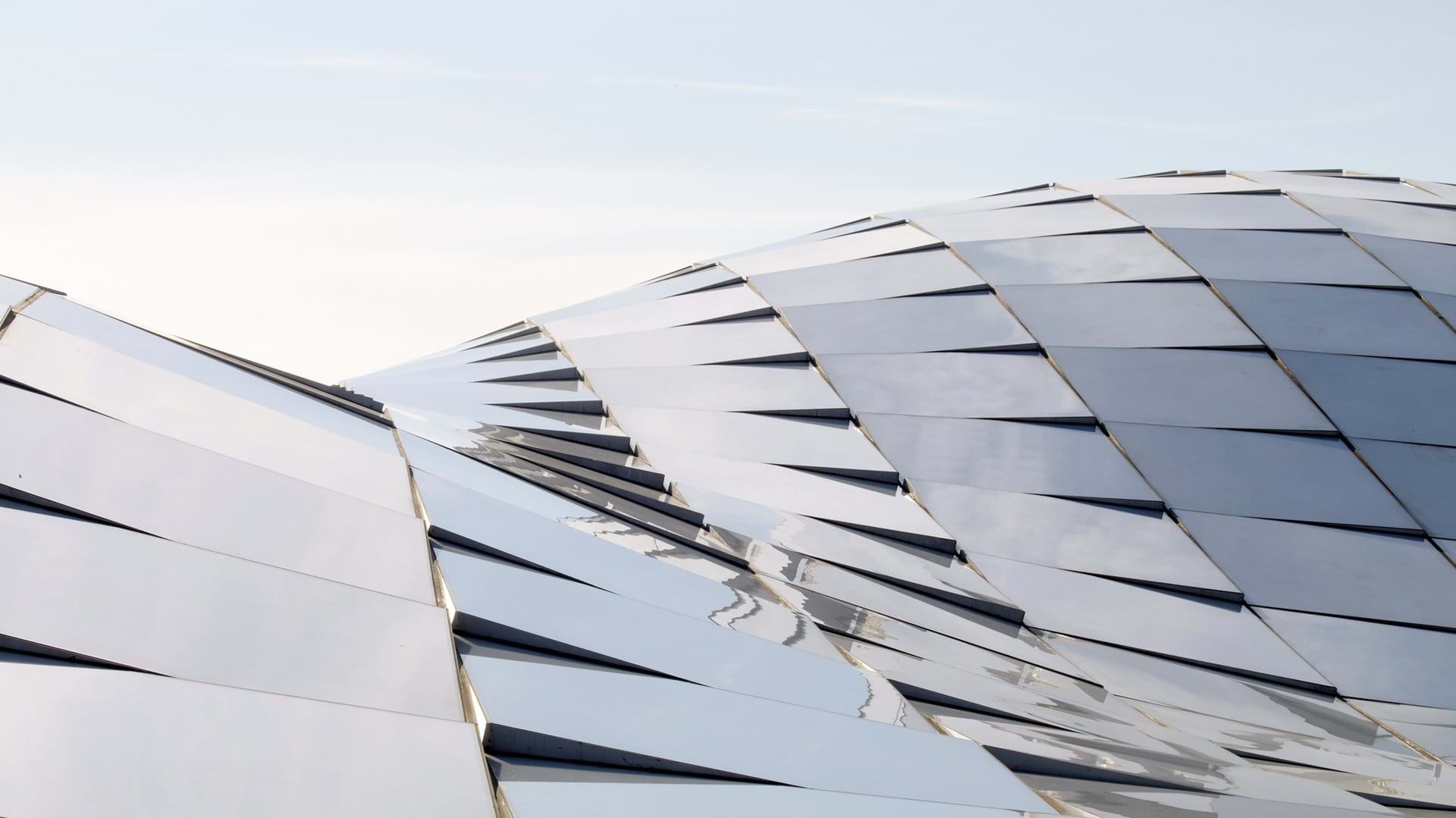
🔨 Planarization
To protect the educational and research activities underneath from the inclement weather and to permit natural daylighting, a translucent glass cladding system was developed atop the proposed timber gridshell. Since a cladding solution that directly follows the roof’s geometry would result in glass panels that are both non-planar and expensive, a custom planarization algorithm was implemented from scratch. Curvature for every panel, or non-planarity more concretely, is thus measured as the distance from the vertices at their perimeter to their best-fit plane. The algorithm iteratively projects the vertices to the best-fit plane to it until their distance reaches zero. Accordingly, the largest initial non-planarity value of 375 mm was nullified. Although it could have been possible to planarize the gridshell itself as has been done in the past, the dragon skin appearance of another precedent motivated the chosen approach and further enriches the aesthetic impact of the new roof over the Engineering Courtyard.
🔍 References
[1] Adriaenssens, S. and Barnes, M. (2001). Tensegrity spline beam and grid shell structures. Engineering Structures, Volume 23, Issue 1, Pages 29-36, ISSN 0141-0296, https://doi.org/10.1016/S0141-0296(00)00019-5.
[2] Adriaenssens, S., & Rhode-Barbarigos, L. (2013). Form-finding and analysis of bending-active systems using dynamic relaxation. In Textile Composites and Inflatable Structures VI - Proceedings of the 6th International Conference on Textile Composites and Inflatable Structures, Structures Membranes 2013 (pp. 51-61). (Textile Composites and Inflatable Structures VI - Proceedings of the 6th International Conference on Textile Composites and Inflatable Structures, Structures Membranes 2013).
[3] De Laet L., Veenendaal D., Van Mele T., Mollaert M. and Block P. (2013). Bending incorporated: designing tension structures by integrating bending-active elements. Proceedings of Tensinet Symposium 2013, Istanbul, Turkey.
[4] Mele, T. Van, Casas, G., Rust, R., & Bernhard, M. (2020). compas-dev/compas: COMPAS 0.12.4. https://doi.org/10.5281/ZENODO.3579440
[5] Churkina, G., Organschi, A., Reyer, C.P.O. et al. Buildings as a global carbon sink. Nat Sustain (2020). https://doi.org/10.1038/s41893-019-0462-4